I2C signals
On the Mega 2560, use pins 20 (SDA) and 21 (SCL). The connectors labelled SDA and SCL on the R3 header carry the same signals.

Connect your first servo and LED. Check the controller pins and the separate servo power supply.
The Arduino powers the module's logic, while a separate 5 V power supply feeds the servo. The LED connects directly to CH15. The resistor is built into the module.
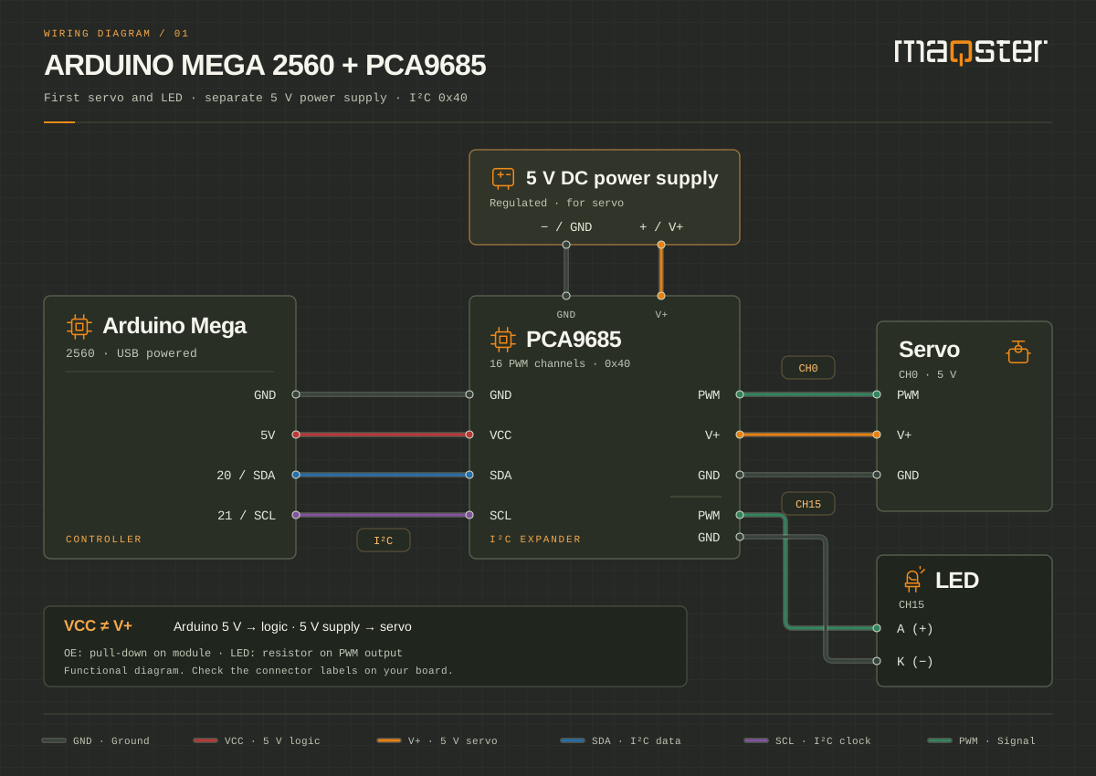
Colour helps you trace a wire. Pin labels determine the connection.
| Signal | From | To |
|---|---|---|
| GND | Arduino Mega 2560 · GND | PCA1 · GND (left connector)Common ground for logic and servo power. |
| VCC | Arduino Mega 2560 · 5V | PCA1 · VCC (left connector) |
| SDA | Arduino Mega 2560 · 20 / SDA | PCA1 · SDA (left connector) |
| SCL | Arduino Mega 2560 · 21 / SCL | PCA1 · SCL (left connector) |
| GND | Power supply · − (GND) | PCA1 · GND terminal |
| V+ | Power supply · +5 V | PCA1 · V+ terminalV+ powers the servos, not the PCA9685 logic. |
| PWM | PCA1 · CH0 PWM | Servo · signal |
| V+ | PCA1 · CH0 V+ | Servo · +5 V |
| GND | PCA1 · CH0 GND | Servo · GND |
| PWM | PCA1 · CH15 PWM | LED · anode (+)No additional resistor. The diagram assumes a module with a series resistor on the PWM output. |
| GND | LED · cathode (−) | PCA1 · CH15 GND |
On the Mega 2560, use pins 20 (SDA) and 21 (SCL). The connectors labelled SDA and SCL on the R3 header carry the same signals.
VCC supplies the PCA9685 logic from the Arduino 5 V pin. V+ is a separate 5 V rail for the servo. Connect the grounds, but do not connect V+ to Arduino 5 V or Vin. The Arduino is powered via USB in this setup.
The diagram covers a board with built-in series resistors on the PWM outputs. The LED connects to CH15 and GND without an additional resistor. Choose an LED suited to the module's output specifications. All PCA9685 channels use the same PWM frequency. Set the frequency required by the servo, usually around 50-60 Hz. The LED may flicker when dimmed at this frequency. Use a separate PCA9685 for a higher LED frequency.
Disconnect power during assembly. Check the pin labels on your specific module and the LED polarity. Servo wire colours vary by manufacturer. The drawing shows a module with OE pulled to ground by default; on another module, connect OE to GND according to its documentation.
Pinouts and connection rules have been checked against manufacturer documentation.