
DIAGRAMS / Raspberry Pi

Connecting multiple PCA9685 modules

Expand the number of channels. See the shared I2C bus and two ways to power the modules.

  1. 01Choose a system
  2. 02Choose a diagram
  3. 03Connect the devices
Selected systemRaspberry Pi
Change system
SELECTED VARIANT

Two modules, one 5 V power supply

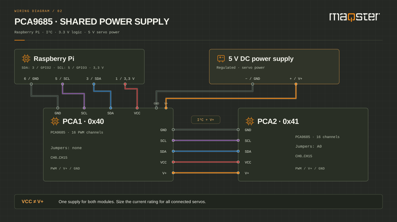
Two modules share the I2C bus and 3.3 V logic from the Raspberry Pi. A separate 5 V power supply feeds the servos via V+.

WIRING DIAGRAM
Raspberry Pi: pin 1 (3.3 V) to VCC, pin 3 (GPIO2 / SDA1) to SDA, pin 5 (GPIO3 / SCL1) to SCL, pin 6 to GND. Two PCA9685 modules: 0x40 and 0x41, connected via GND, SCL, SDA, VCC and V+. One separate 5 V servo power supply.
The drawing shows electrical connections. Connector positions may vary by board manufacturer. Enlarge to read the pin labels.
  • GND Common ground
  • VCC 3.3 V logic
  • V+ 5 V servos
  • SDA I2C data
  • SCL I2C clock
PIN BY PIN

Wiring table

Colour helps you trace a wire. Pin labels determine the connection.

Connections for the shared power supply variant
SignalFromTo
GNDRaspberry Pi · pin 6 (GND)PCA1 · GND (left connector)
SCLRaspberry Pi · pin 5 (GPIO3 / SCL1)PCA1 · SCL (left connector)
SDARaspberry Pi · pin 3 (GPIO2 / SDA1)PCA1 · SDA (left connector)
VCCRaspberry Pi · pin 1 (3.3 V)PCA1 · VCC (left connector)
GNDPower supply A · − (GND)PCA1 · GND terminal
V+Power supply A · +5 VPCA1 · V+ terminal
GNDPCA1 · GND (right connector)PCA2 · GND (left connector)
SCLPCA1 · SCL (right connector)PCA2 · SCL (left connector)
SDAPCA1 · SDA (right connector)PCA2 · SDA (left connector)
VCCPCA1 · VCC (right connector)PCA2 · VCC (left connector)
V+PCA1 · V+ (right connector)PCA2 · V+ (left connector)Shared power within the group.
HOW TO WIRE THE CIRCUIT

Things to remember

01

Physical pins and GPIO

Use physical pins on the 40-pin header: 1 (3.3 V), 3 (GPIO2 / SDA1), 5 (GPIO3 / SCL1) and 6 (GND). A GPIO number is not its position on the header. Check the location of pin 1 on your board. This circuit is not for Raspberry Pi Pico or early boards with a 26-pin header.

02

3.3 V logic and servo power

Connect module VCC to Raspberry Pi 3.3 V. SDA and SCL may only be pulled up to 3.3 V. Do not connect VCC to V+ or the Pi's 5 V pins. Power servos separately via V+ and connect the grounds. A dedicated power supply powers the Raspberry Pi through its power socket. The PWM signal is at 3.3 V, so the servo must support it.

03

Enable I2C in Raspberry Pi OS

Run sudo raspi-config, choose Interface Options, then I2C and Yes. A module without address jumpers has address 0x40. In the control software, select bus I2C1 and the module's address. These are electrical wiring instructions; control requires software supporting PCA9685 on Raspberry Pi.

04

Each module's address

PCA1: 0x40, no jumpers. PCA2: 0x41, A0 bridged. Bridge address pads with power disconnected. Use 7-bit addresses in the configuration.

05

Shared 5 V rail

V+ and GND distribute servo power to both modules. VCC at 3.3 V comes from the Raspberry Pi and powers logic only. At higher currents, run separate wires from the same power supply to both modules' terminals instead of loading the pass-through connectors.

06

It is still one I2C bus

The connectors on both sides of the module are electrically parallel. Connecting modules one after another is not serial data transmission between chips. Keep I2C wires as short as possible. When expanding, check wire capacitance and the combined pull-up resistance on the modules.

07

Sizing for the load

Allow for all servos' startup and stall current, voltage drops and the current rating of connectors and tracks on the specific board. Do not power servos from Raspberry Pi 5 V pins. Leave OE unconnected only on modules with a factory-fitted pull-down resistor.

Enlarged view. On a small screen, scroll the diagram horizontally.

FREE · NEWSLETTER AND LAUNCH

We will let you know when
the app is ready

Sign up for the newsletter. After launch, we will email you a link to an account where you can download the app.

LET'S TALK ABOUT PRO

Your idea
PRO possibilities

Tell us about your model. We will help you choose the right application features and work out where to start.

  • Scenes and device control
  • Automation and integrations
  • A conversation about your project
maqsterLight. Motion. Sound.

We will reply to the email address you provide. Privacy policy.

Contact

Discuss control for your model

Tell us what you would like to do with your model layout. After a consultation, we will prepare a complete system tailored to your project.

  • Device and scene plan
  • Local control and configuration backups
  • Controllers, protocols and integrations