Each module's address
PCA1: 0x40, no jumpers. PCA2: 0x41, A0 bridged. Bridge address pads with power disconnected. Use 7-bit addresses in the configuration.

Expand the number of channels. See the shared I2C bus and two ways to power the modules.
Five wires connect the two modules: GND, SCL, SDA, VCC and V+. Logic power comes from the Arduino, while the servos use a shared 5 V power supply.
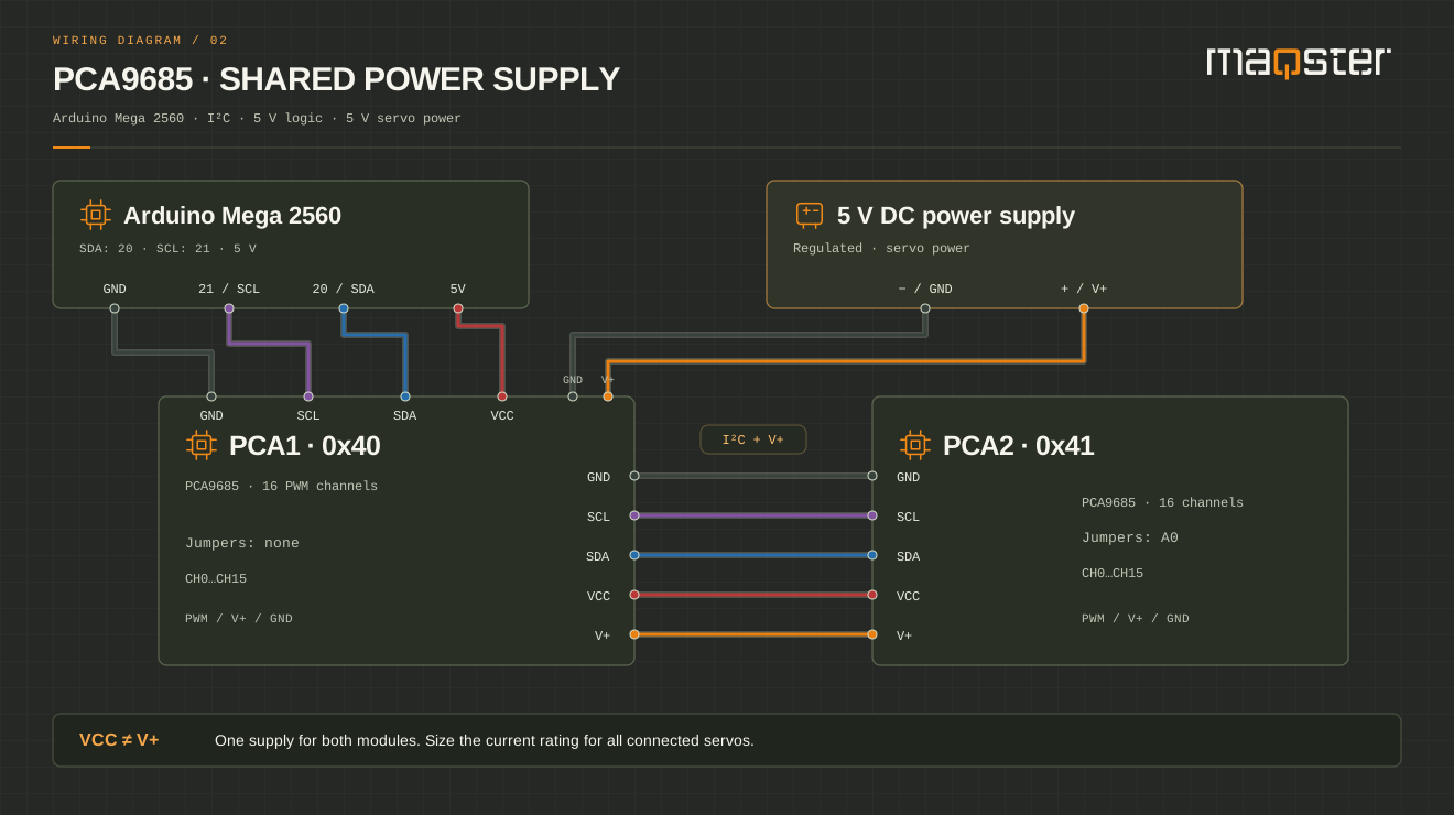
Colour helps you trace a wire. Pin labels determine the connection.
| Signal | From | To |
|---|---|---|
| GND | Arduino Mega 2560 · GND | PCA1 · GND (left connector) |
| SCL | Arduino Mega 2560 · 21 / SCL | PCA1 · SCL (left connector) |
| SDA | Arduino Mega 2560 · 20 / SDA | PCA1 · SDA (left connector) |
| VCC | Arduino Mega 2560 · 5 V (VCC) | PCA1 · VCC (left connector) |
| GND | Power supply A · − (GND) | PCA1 · GND terminal |
| V+ | Power supply A · +5 V | PCA1 · V+ terminal |
| GND | PCA1 · GND (right connector) | PCA2 · GND (left connector) |
| SCL | PCA1 · SCL (right connector) | PCA2 · SCL (left connector) |
| SDA | PCA1 · SDA (right connector) | PCA2 · SDA (left connector) |
| VCC | PCA1 · VCC (right connector) | PCA2 · VCC (left connector) |
| V+ | PCA1 · V+ (right connector) | PCA2 · V+ (left connector)Shared power within the group. |
PCA1: 0x40, no jumpers. PCA2: 0x41, A0 bridged. Bridge address pads with power disconnected. Use 7-bit addresses in the configuration.
V+ and GND distribute servo power to both modules. VCC comes from the Arduino and powers logic only. At higher currents, run separate wires from the same power supply to both modules' terminals instead of loading the pass-through connectors.
The connectors on both sides of the module are electrically parallel. Connecting modules one after another is not serial data transmission between chips. Keep I2C wires as short as possible. When expanding, check wire capacitance and the combined pull-up resistance on the modules.
Allow for all servos' startup and stall current, voltage drops and the current rating of connectors and tracks on the specific board. Do not power servos from the Arduino 5 V pin. Leave OE unconnected only on modules with a factory-fitted pull-down resistor.
Pinouts and connection rules have been checked against manufacturer documentation.